Abstract
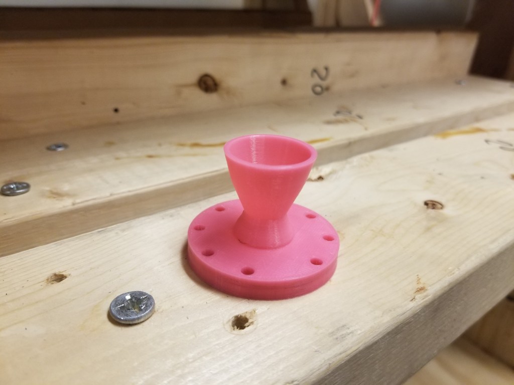
For a competition within the Boston University Rocket Propulsion Group (BURPG), my friend (Esther Ye) and I designed, 3D printed, and tested a cold gas thruster. Cold Gas Thrusters are used as part of roll control systems on rockets. They expel high pressure gas through a nozzle to produce thrust.
In this competition, each Cold Gas Thruster was optimized for 45,000 ft above sea level and sought to minimize mass while attempting to maximize thrust and specific impulse (Isp).
My role in this project was to construct the mathematical model and to design the nozzle in Solidworks.
Design Process
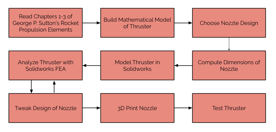
Math Model
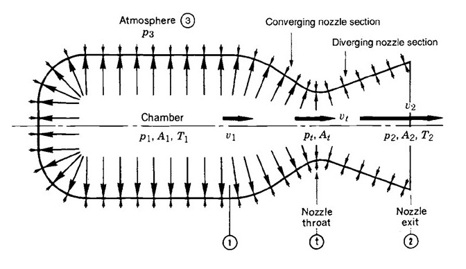
The design of our cold gas thruster was largely driven by our mathematical model. We modeled our thruster as an adiabatic (no heat transfer) and isentropic (no change in entropy) nozzle. From our calculations, we wanted to know the relationship between the throat area of the nozzle and the exit area, a quantity called the Area Ratio. Together with the smallest system diameter, we could use the Area Ratio to determine the dimensions of the rest of the nozzle.
Expected Performance
| Parameter | Description | Value | Unit |
|---|---|---|---|
| Isp | Specific Impulse is a measure of how effeciently the thruster uses the propellant. | 41.9775 | s |
| F | The amount of thrust produced. | 70.71 | N |
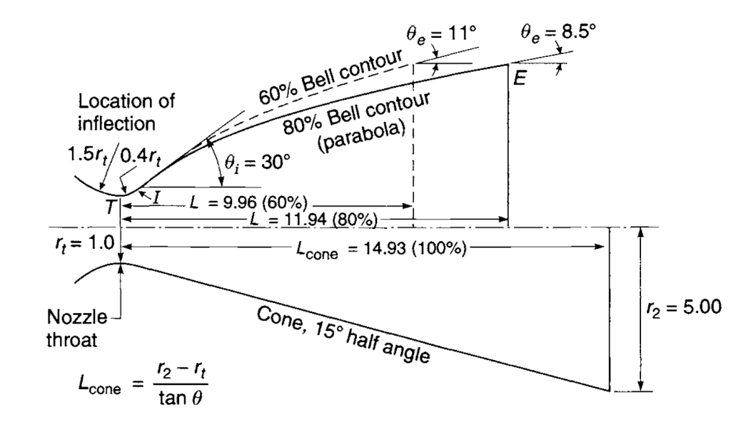
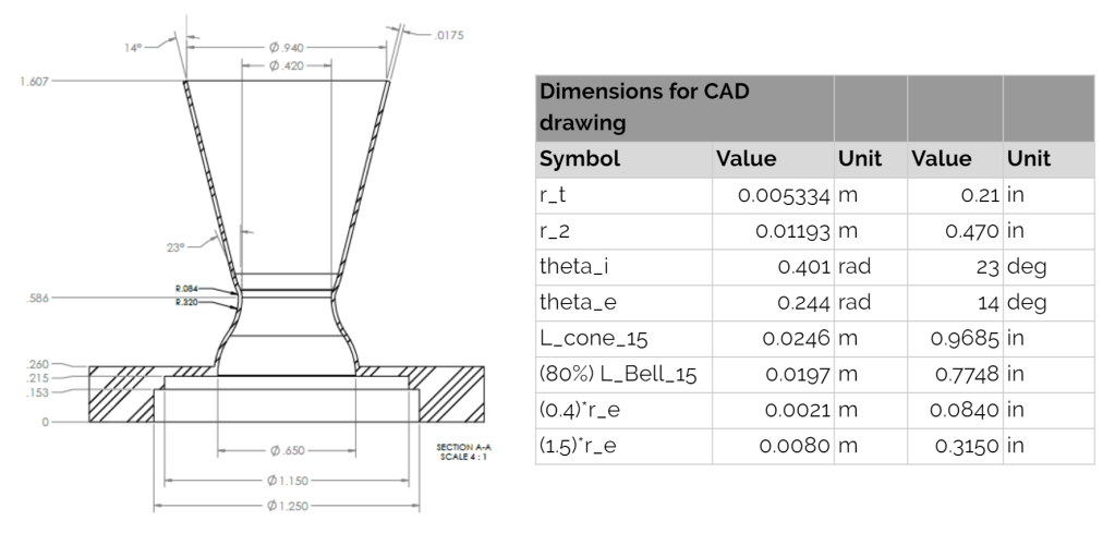
Nozzle Shape
We chose a 80% bell nozzle with a 23 degree angle at the throat and a 14 degree exit angle. Compared to a traditional conical nozzle, the bell nozzle provides a similar performance at a shorter length, thus minimizing the mass of the overall system.
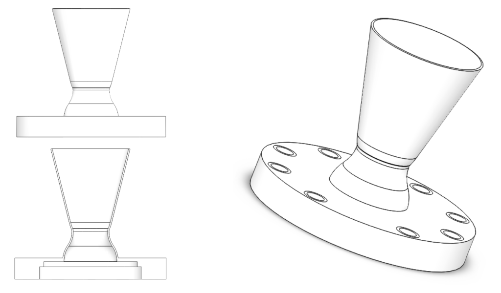
Solidworks Model & FEA Analysis
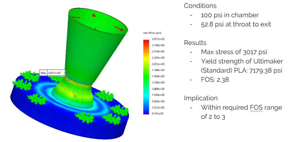
After designing and modeling the performance of our nozzle, we modeled our thruster in Solidworks. We also used the Solidworks FEA capability to ensure that we maintained a factor of safety between 2 and 3. The factor of safety represents how close the max stress on the component is from the yield strength of the material itself. In our case, we were using PLA plastic since we were 3D printing our thruster.
Reflection
My favorite part of the design process was building the mathematical model of the thruster’s performance. I really enjoyed connecting what I had learned from Rocket Propulsion Elements to the optimization of a nozzle. In the process, I was able to understand how parameters like the exit area or the mass flow rate of the propellant would impact the overall performance of the system.
